The board itself was not especially complicated:

Fortunately there was already a VSSOP footprint available in KiCad so that made it a bit easier. Since then I have gained a bit more experience with adding footprints to KiCad and I realize if I'd made my own I probably would have made the pads a little longer so as to make the placement easier.
The boards arrived back from OSH Park last week and they were, as always, quite beautiful with their gold and purple finish:

I broke out my USB microscope and began soldering. Almost immediately I began to realize how difficult this task would be. Not only are the pins very small but the whole package is so light that even the lightest touch would displace it. True the package is actually a bit bigger than, say, an 805 resistor or capacitor but in those cases the pins and pads are quite large.
Most advice on the Internet for soldering this type of SMD package is to first tack down one corner, to use lots of flux and clean up with copper anti-soldering braid. I ended up doing all of those things, but found they are easier said than done. I tinned the pads, cleaned up any bridged pins with braid then placed the IC and holding it down with tweezers very firmly from the top I managed to blob a bit of solder in one corner. The pins looked roughly lined up, not perfect but good enough. I recently got some 0.31mm diameter solder and that was useful. Then fluxed generously again and dragged some solder across the other side. More flux and then lots of time spent with braid to clean up. I've realized the hardest part is getting the braid in actually the right place. It needs to be right up against the pins and for such a small device that's not easy. Generally a little bit of smoke (the good type) showed when I was actually making contact with the solder. Fortunately testing for bridges was pretty easy, I could simply check each pair of pads on the DPI module with a multimeter. There was one stubborn bridge but I got it in the end by briefly heating the bridge directly with the iron before applying the braid. Once all the bridges were gone I could check continuity with the between the actual IC and the DIP pads and they all seemed fine.
Here are some photos of the final result:

As you can see the soldering tip looks huge! These photos were taken before I cleaned up the board so everything looks filthy, including the soldering iron! There's nothing like a close up view to show how messy things really are.
From the side things look a little better:

It's pretty clear the pins are soldered and lined up reasonably well with the pads.
Finally to give it some scale - here's one with a US dime:
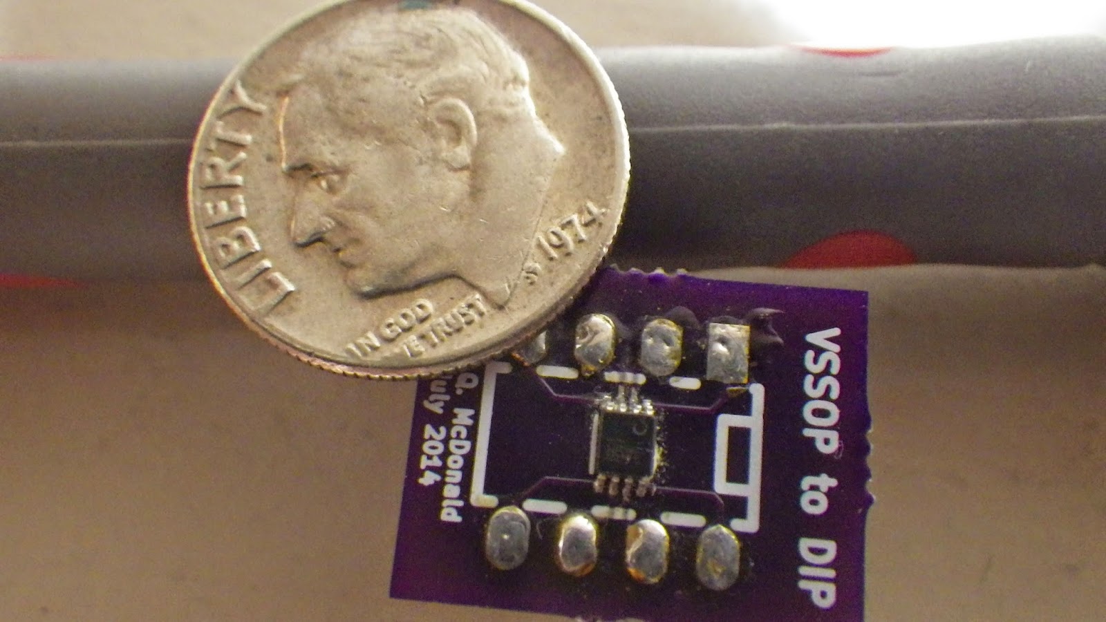
After all that effort it would have been extremely disappointing if it hadn't actually worked. Fortunately there was no problem. I hooked the logic pins up to a couple of Arduino pins (with pull down resistors, not sure if they are absolutely necessary but they seemed like a good investment). It worked perfectly first time. There are four states accessible with the two bits - all off and any one of the three output connected to the common. I used it to switch the output from the three waveshapers I have and it was great to be able to hear the waveform change as I pressed the push button on the rotary encoder. Although there are several SMT packages I'm planning to use I hope this will be the smallest by far.
No comments:
Post a Comment